THERM-O-MATIC

Coil%20holder

Therm-O-Matic Maxi Version

The Maxi system is designed to inspect and mark defect correctly on not straightened products. Maximum bending and end condition. The position of the billet/bar can be off +75 mm and -20 mm from the ideal position and be anywhere in a dynamic area. The position measuring system covers the area and controls the coil servo keeping the coil safe and centered on the billet/bar. The coil servo repositions the coil automatically when changing billet/bar sizes. When new inspection parameters are entered or downloaded.
IMG_6002

Therm-O-Matic Mini version

The Mini-version is a simplified version designed to inspect straightened billets and bars. Billet position measuring and coil servo is not required. The coil is mounted in fixed position on the scanner frame. The marking station is simplified with one row of paint guns mounted in the same way as maxi version with frame servo for positioning vertically according to product size. The pitch between paint guns depend on the customers request, 16,2 mm, 25 mm or one gun per 90 ° sector or one paint gun per side on squares. The marking accuracy depends on the bending and the distance between paint guns.
Paintgunns_kopi

Defect Marking

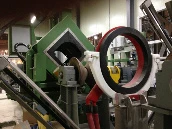
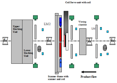
The marking system consist of 2 stationary lower marking blocks and 2 upper marking blocks mounted on a frame which is positioned vertically to position the block in correct position according to billet/bar size
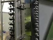
The marking block is equipped with required paint pistols, with 16 mm pitch, to cover the – 20 mm bending down (between rollers) the billet/bar size and the 75 mm bending upwards.
The billet/bar position measuring system measure the position of the billet/bar and send the marking signal to the paint gun in the best poison to mark the defect most accurately. It also assures that defects in corners miss if the billet/bar is bended.

The strongpoint’s of Therm-O-Matic® (T-O-M) is:

  • Large limits for bending and end condition
  • Automatic operation with equal sensitivity on the circumference of the product.
  • Contact less and inline operation
  • Mark defects true to position
  • Reliable detection thresholds.
  • Safeguarding of the equipment.
  • Independent of operator qualification
Layout_of_components_in_the_inspection_line_of_the_T-O-M_Maxi_version800x600-2
Special functions and design is implemented to make a reliable industrial machine out of a very simple inspection method. Equipment and sensors required to be in the line is mounted on  frames in between rollers.

Between roller 1 & 2:

  • Speed measuring system 1:  Measure the speed of the product from the first end enters.
  • System to measure billet/bar dimensions: The dimensions are measured from both sides to stop the line when:
  • The size is outside of the allowable size range of the coil for protection.
  • The size is within the size range, but different from what the machine is set up to inspect.
  • 2 billets/bars are loaded at the same time.

Between roller 2 & 3:

  • Spraying nozzle for the wetting of the surface.
  • System to measurement of billet/bar position to control the coil position, (TOM Maxi)
  • HF coil mounted on a hydraulic servo
  • Hydraulic servo for positioning of coil: (TOM Maxi)
  • For centering of the coil to obtain equal HF-excitation of the surface.
  • For protection of the coil
  • For automatic vertical positioning when changing sizes. (TOM Maxi)
  • Scanner frame with electrical servo for vertical positioning of scanner and background plates.

Between roller 3 & 4:

  • Speed measuring system 2: The speed control switches to wheel 2 when the front end enters the marking station.
  • The lower 2 marking blocks (No 2 and 3) are mounted on chariots which can be pulled out to gain easy access to the paint guns for cleaning.
  • The 2 upper marking blocks are mounted on a frame for vertical positioning according to billet/bar size.